OCTO Hub
Detail Diagram
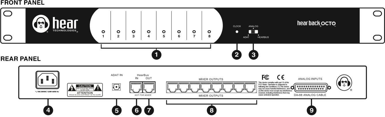
1 | Audio Input Channels 1-8 Level LED Metering | 6 | HearBus Input |
2 | HearBus Clock Status Indicator | 7 | HearBus Output |
3 | Input Selector Switch | 8 | Hear Back OCTO Mixer Outputs |
4 | AC Power Input | 9 | Analog Inputs |
5 | ADAT Optical Input |
Features
- Three switch selectable 8-channel input sources:
- ADAT Optical
- Analog
- HearBus
- 24-bit A/D converters
- Digital input sample rates: 44.1 KHz or 48 KHz
- Less than 1.5 milliseconds total system delay (latency)
- Multi-color, four-level metering
- Standard CAT5e/6 delivers power and signals to Mixers
- Daisy-chain for very large systems
- Internal universal power supply
- 1 RU chassis
Hub Inputs
1. ADAT®
The ADAT input can be connected to digital audio workstations, digital recorders, or digital mixers using a standard TOS-Link optical cable. The Hear Technologies Extreme Extender ADAT OUT (XOUT) is a convenient way to convert the OCTO Hear Bus output to ADAT at a distance of up to 500 feet.
The OCTO Hub ADAT input and XOUT ADAT outputs may use Optical cables up to 25 feet in length.
2. HearBus®
The HearBus permits daisy-chaining of multiple Hubs up to 500 feet apart using the HearBus input and HearBus output. This HearBus is great for inter-studio or stage-to stage connections, as well as daisy chaining for very large systems. Use Hear Technologies CAT6 cables, available in 50 foot lengths.
3. Analog
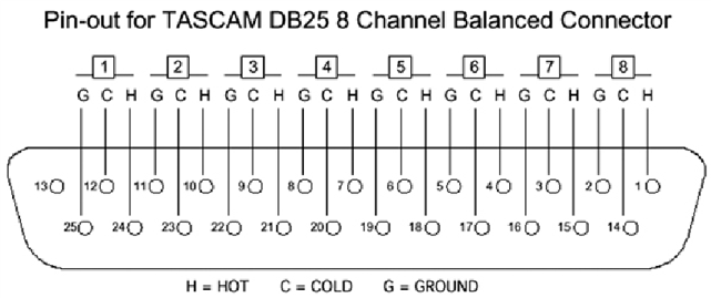
Analog inputs are fully balanced and are connected using a standard Tascam DA-88 style Analog cable, such as the Hear Back Analog cable.
DB25 cable pin-outs are wired as shown below:
Use only DA-88 Analog. Do not use TDIF.
Input Selector Switch
The input selector switch gives the user a simple way to select any one of the three input sources without a patch bay, router or rewiring.
Hub Outputs
The Hub has Mixer outputs which each deliver digital audio, ground and +/- 17.5VDC. Each of the eight Hub outputs must make a "home run" to a Mixer, with a maximum distance of 200 feet. Outputs not in use should be disconnected at the Hub. Use CAT5e or CAT6 cable cable using the standard T568B punchdown with no crossover.
Mixer RJ45 Pinouts
| Pin | Function | Pin | Function |
|---|---|---|---|
| 1 | Digital Audio + | 5 | +17.5VDC |
| 2 | Digital Audio - | 6 | Ground |
| 3 | Ground | 7 | +17.5VDC |
| 4 | +17.5VDC | 8 | +17.5VDC |
Each of the eight Hub Mixer outputs has a solid-state automatically resettable fuse in-line with the power supply outputs to prevent power supply damage. In the event of a shorted cable or broken Mixer, the PTC fuses go to high impedance permitting other Mixers to function while protecting the power supply from the faulty output.
The main AC input is connected using a standard IEC320 cable.
The universal power supply is designed to operate from 90 to
264VAC at 50 to 60Hz. The AC input circuit is internally fused.
Input Metering
The Hub features a unique input metering circuit consisting of a single RGB LED for each of the eight inputs. BLUE indicates -32 dBu signal presence, GREEN -10 dBu, YELLOW +4 dBu and RED indicates clip at +16 dBu.